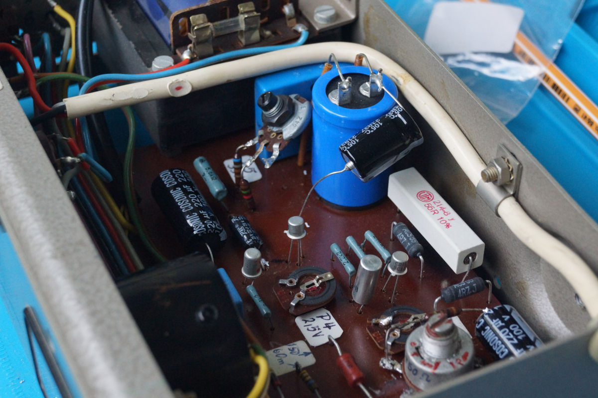
I recently got two Gossen Pantam Konstanter 33 015 lab supplies from the mid to late 60s as shown above. Both of them are their own can of worms and need some fixing. The following describes how I fixed one of them , I’ll do another post once I fix the second one.
This one is peculiar in that someone already had a go with it and “fixed” some of the things, multiple parts have been replaced at some point and there are clear signs of amateur soldering, in that wires have been touched and scorched by a soldering iron.
Getting the schematics
The schematics seem to be only available at radiomuseum.org, fortunately you can now download schematics as a guest without having to pay the membership fee.
Transistor replacement
Someone already replaced the original OC460 germanium transistors with 2N2907A’s. I suspected those were broken and replaced them with BC177A’s. Turns out the 2N2907A were checking out okay, so I kept them for some other project in the future.
Transistor load balancing issue
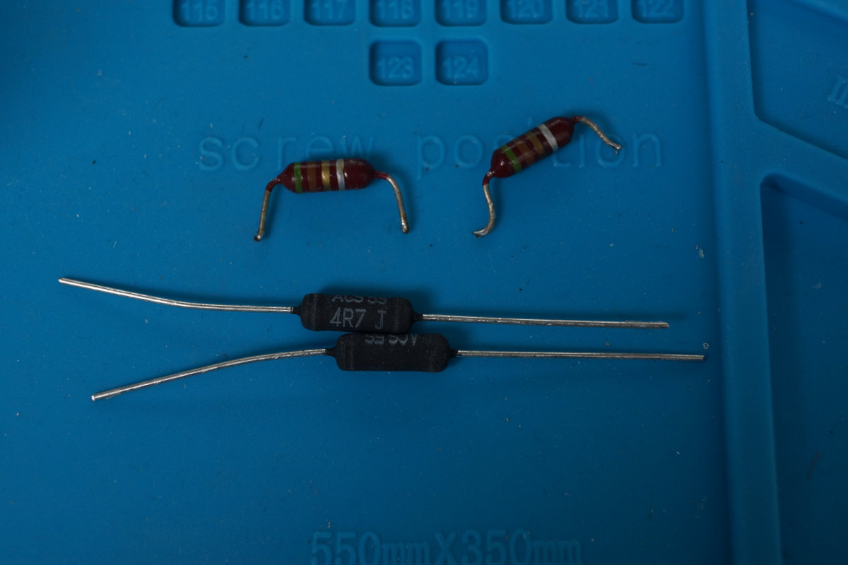
The T2 contains two TO-3 germanium transistors (AZ15). When putting a high load on the unit I noticed that only one of them got hot. Looking at the schematic each of the two emitters go through a 4.7Ω power resistor before being commoned together, this is a traditional way of ensuring the two transistors get loaded similarly. I measured the two resistors in question and noticed that one of them had burn marks and was open circuit. So there we had the problem!
I replaced the 4.7Ω resistors for both transistors (in a pair) with new ones, I used 5W resistors.
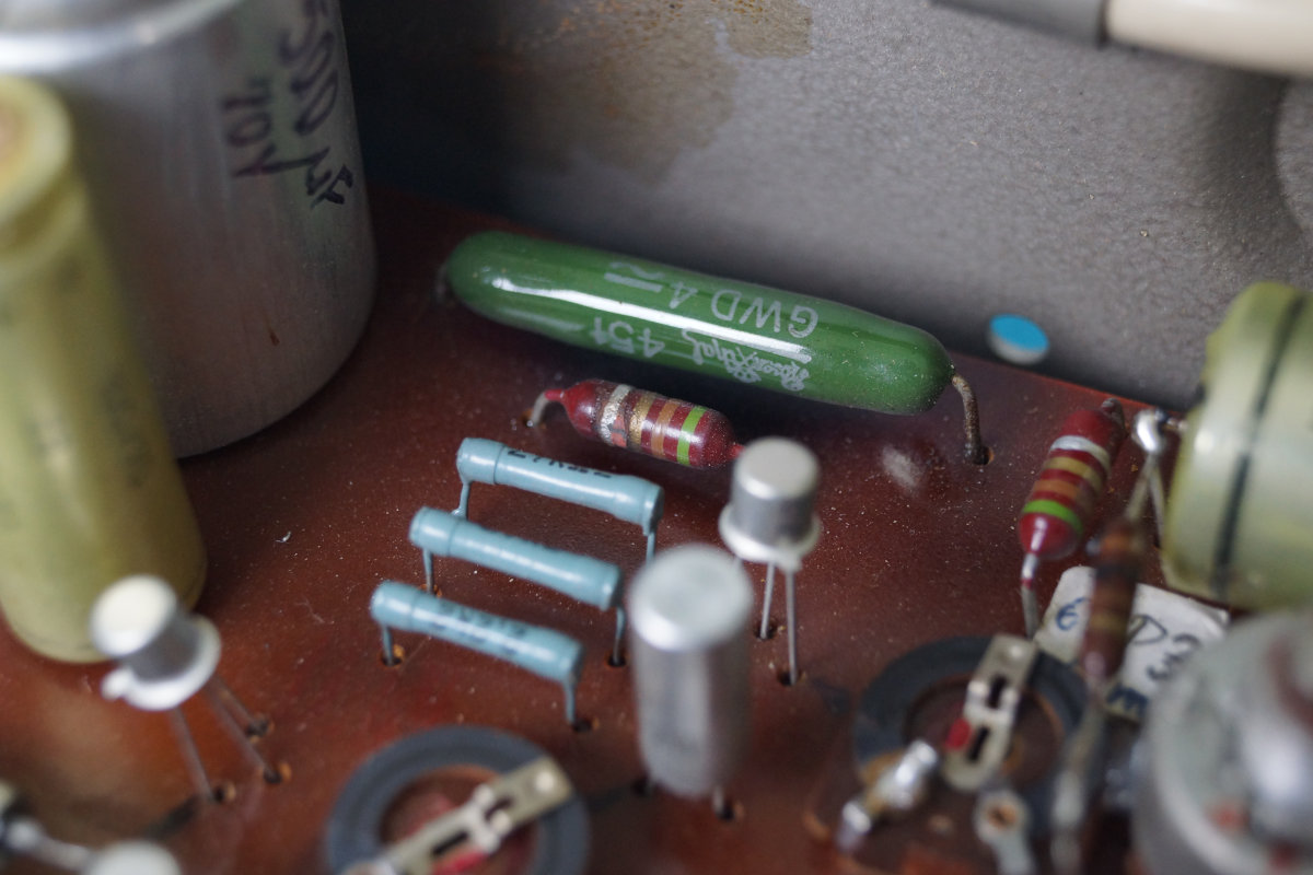

After this both transistors got equally warm meaning they are now loaded in a similar fashion.
Replacing all Electrolytic Capacitors
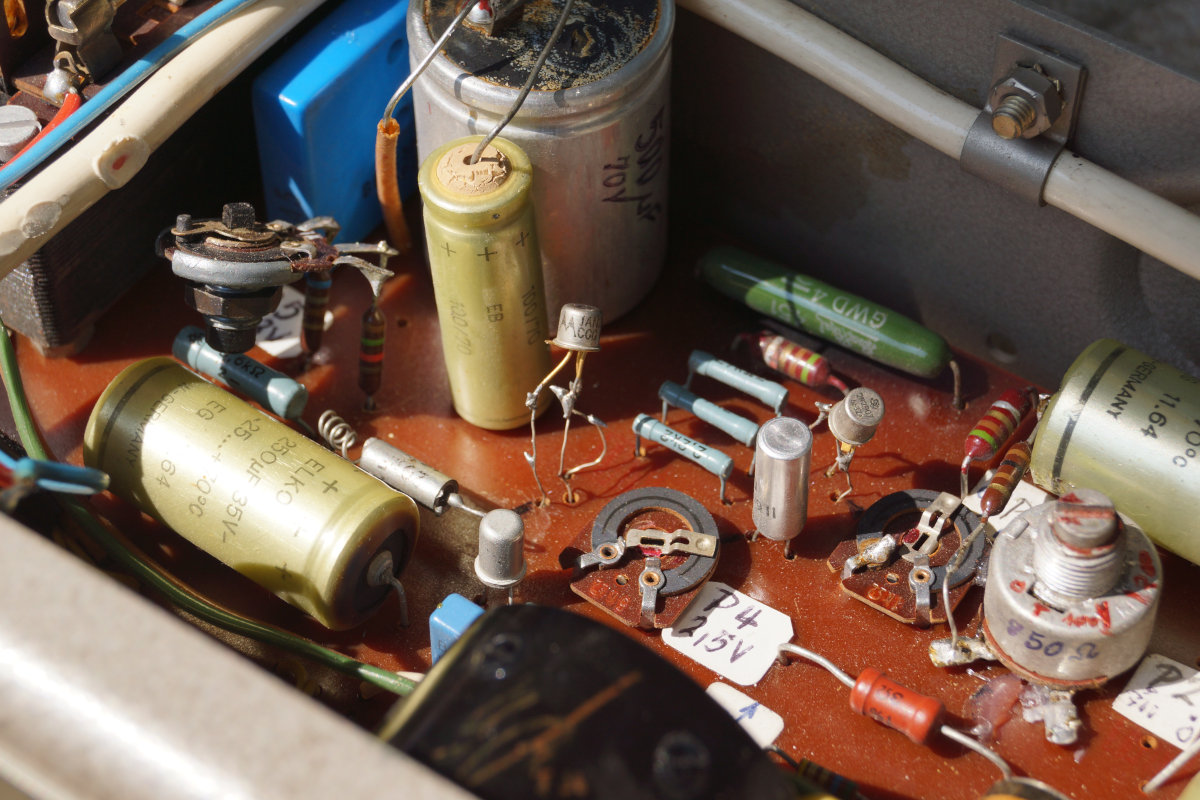
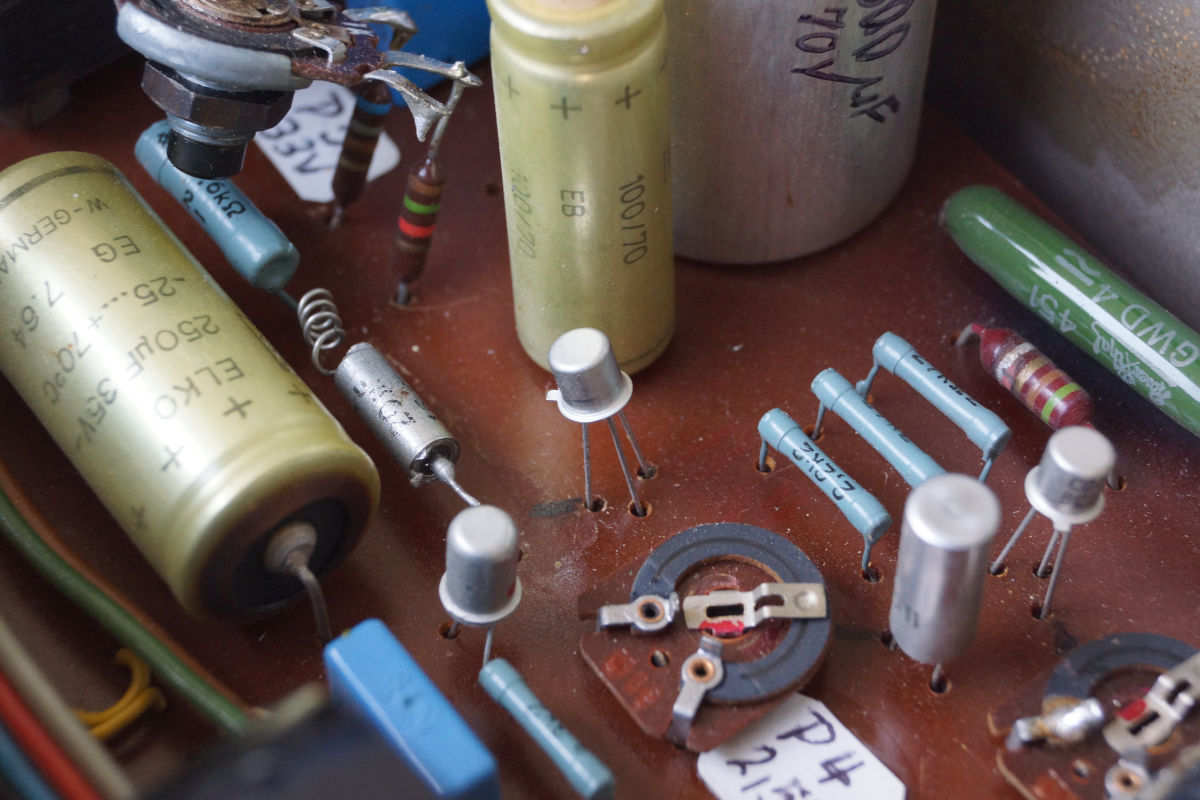
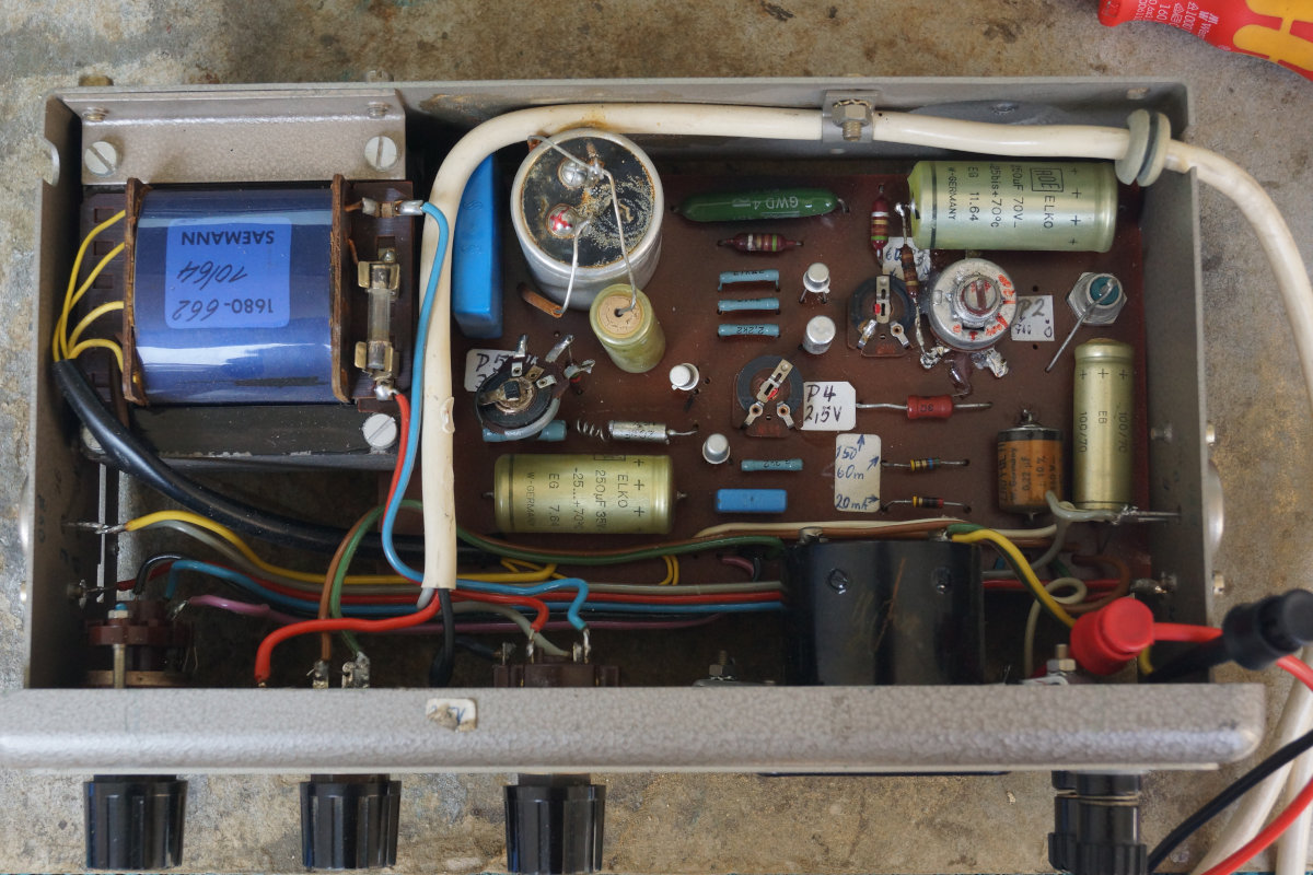
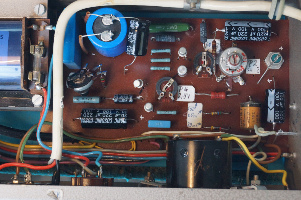
As can be examined from the previous pictures, all of the electrolytic capacitors look bad, almost all of them appear to have vented. Even though they are checking out somewhat fine on my LCR meter, I decided to just replace them all - so I don’t get any nasty surprises in the future.
I replaced the following:
- 1x 500uF 100V with M8 screw
- 2x 100uF 100V axial
- 2x 220uF 100V axial
- 1x 22uF 16V axial
I left the axial 220nF film capacitor alone, as it still looked fine.
The hot resistor
All current coming out of the main storage capacitor runs through a 60Ω resistor which gets excruciatingly hot under high load, I measured over 200°C with my thermocouple meter. So while on it I decided to replace this one with a higher wattage ceramic wire wound resistor, to keep the temperature and thus thermal load to a minimum.
Done
Or almost, I still want to replace that potentiometer next to the blue main storage capacitor, but I didn’t had any fitting ones at hand.