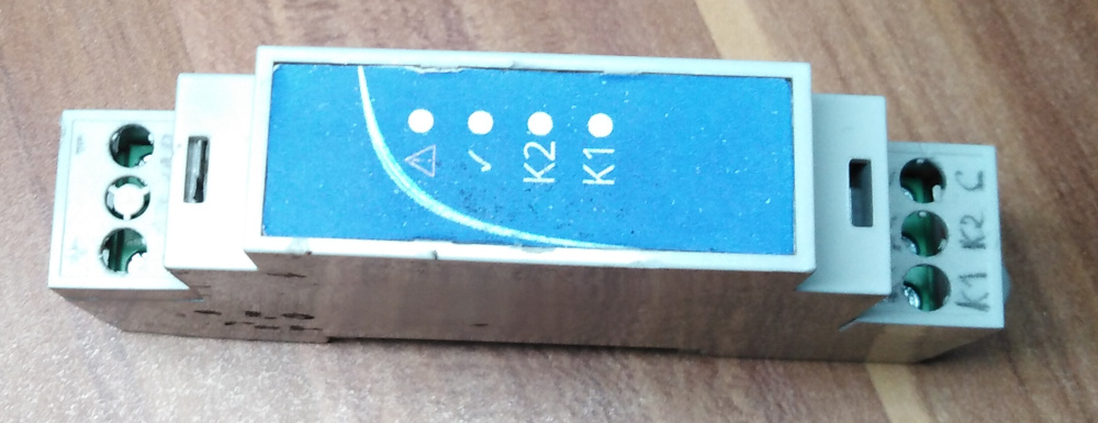
The other day I’ve built myself an ESP8266 WiFi dual-relay for standard DIN rails.
Electronics
Bottom PCB
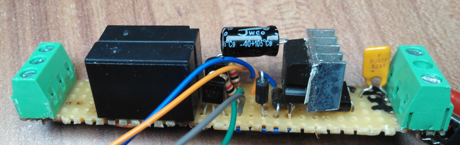
The bottom PCB is fairly simple, input goes through a polyfuse and a bridge rectifier such that I can power it both from 8VAC-12VAC or 12VDC. And then just a 7805 with protection diodes and a heatsink. At 12V the 7805 dissipates around 0.6W of power which doesn’t sound much, but it gets hot.
For the outputs, there are the two 12V relays driving by BC517 darlington transistors and with 1N4148 protection diodes on the bottom side of the PCB. The relays have a common input and each an output on the screw terminal. They are powered directly from the rectified input supply.
Top PCB
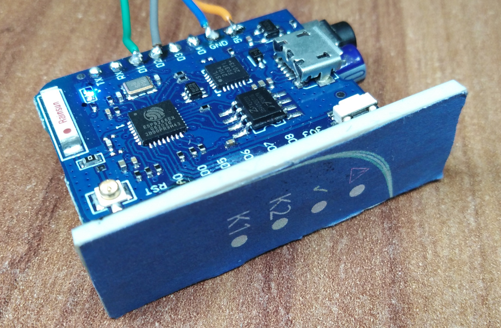
Nothing special, just a D1 Mini Pro board, some LEDs and a resistor array. I furthermore connected the A0 input to a small headphone jack, whose other side is biased to 1.65V so that I can connect and read out CTs (current transformers) with internal burden resistors. Though I have not tested this yet.
The RUN LED blinks during normal operation (like on a PLC), the ERR LED lights up permanently if it cannot connect and flashes briefly on a protocol error.
Firmware
I use the normal ESP8266 webserver, that reacts to REST requests to switch the relays on and off. I added a lockout delay of 5 seconds after a relay has been switched off before it can be switched on. This should avoid the relays or the load from burning out in case my software controlling this messes up.
Software
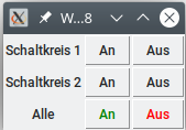
Simple control utility written in Python 3 with TKinter. Sends out the respective REST request for the respective relay.