
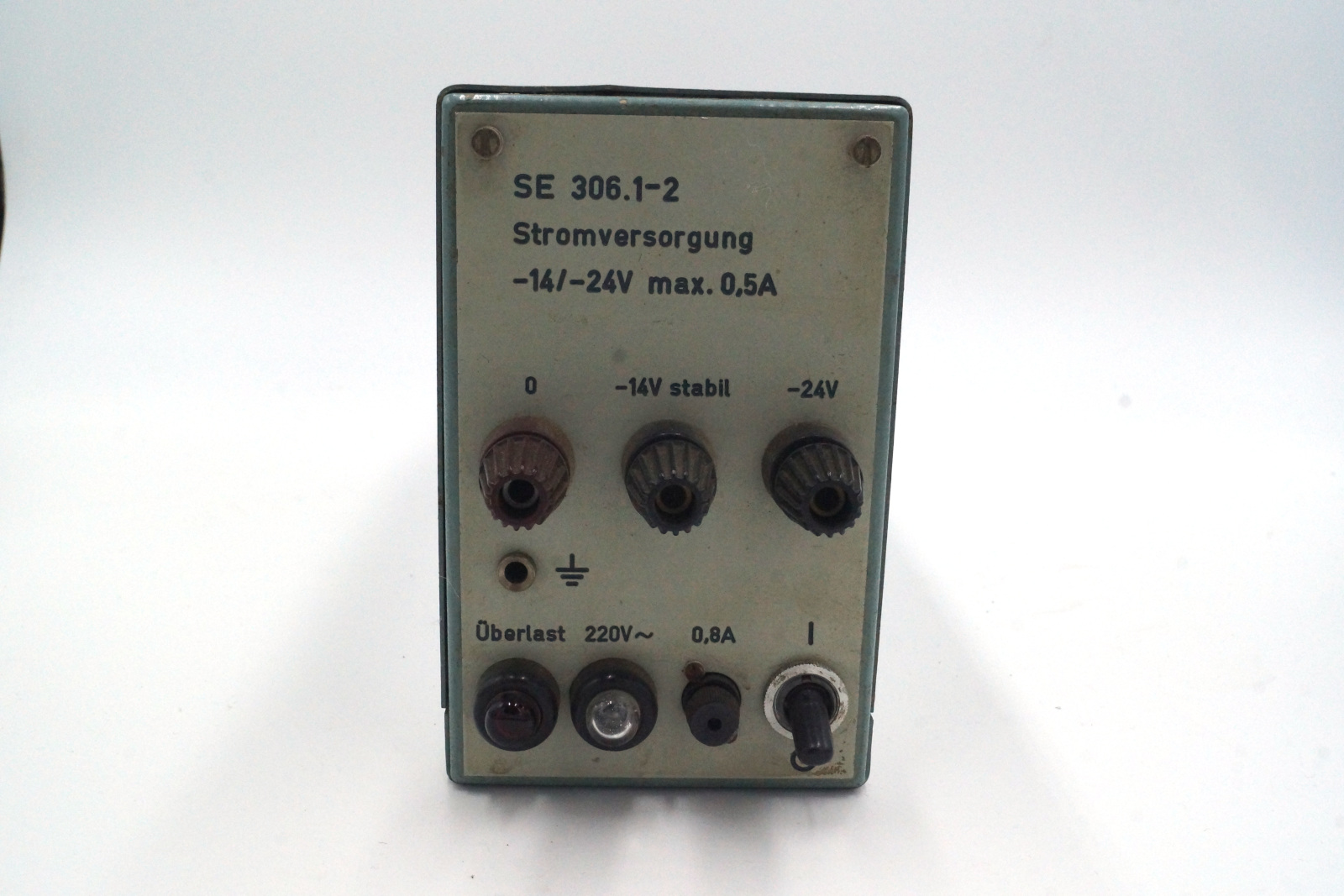
I recently got this old power supply in an untested condition. It has an unregulated -24V DC output, as well as a regulated -14V output, cumulative 500mA max.
It is not really suitable as a laboratory power supply, as over current protection is done using a fuse on the secondary transformer side. A pretty neat feature however is the overload indicator, if the unregulated voltage rail drops too much it will light up way before there is a risk of the fuse blowing.

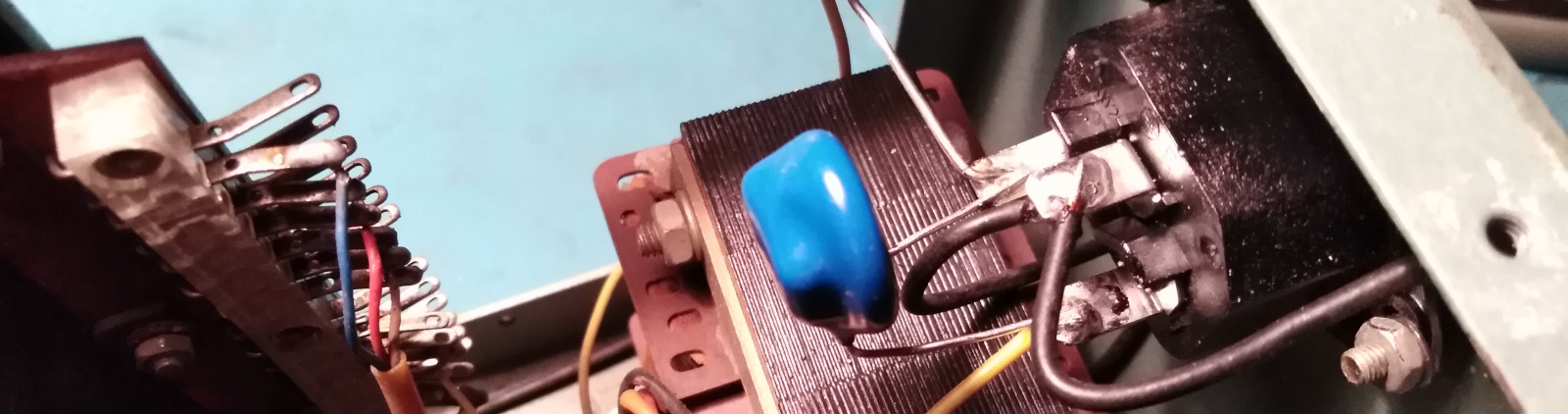
Inside view

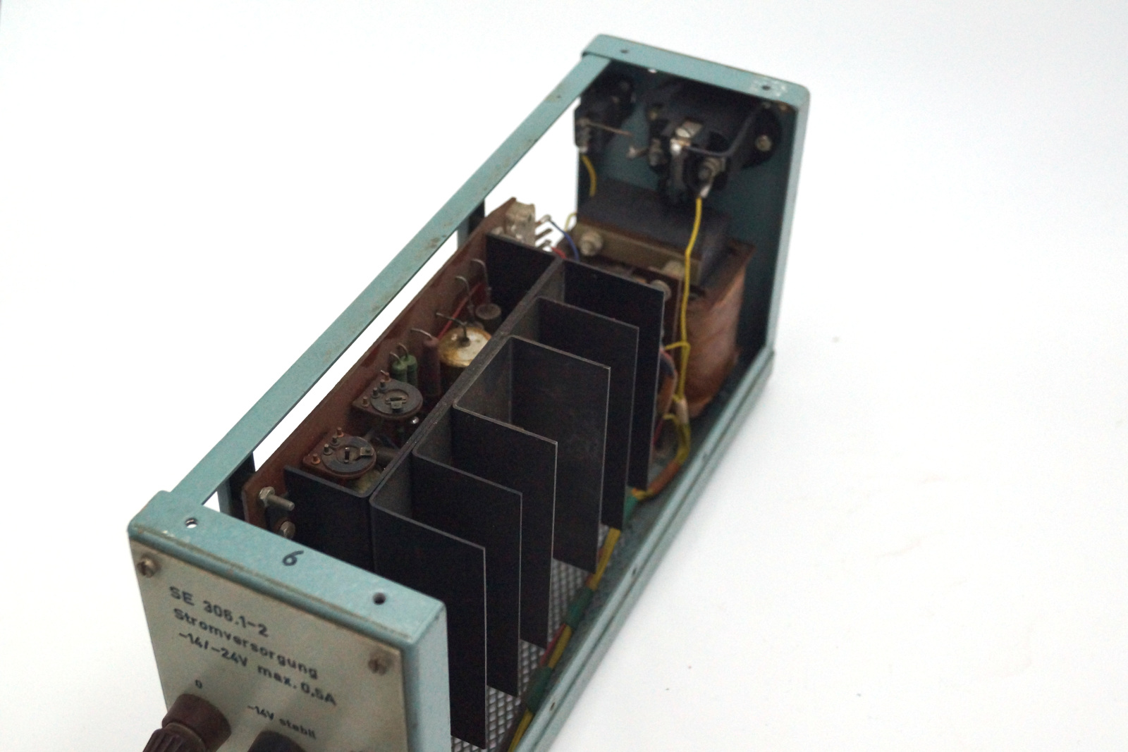

Through the top ventilation opening I could already see a suspicious capacitor.
Repair
I replaced three capacitors: The main storage capacitor which looked suspicious from top was actually vented upon examining it. Another electrolytic capacitor looked fine but I decided to replace that one as well, as well as a 1uF capacitor (probably a film capacitor?) but I wasn’t sure and at the risk of it being an electrolytic capacitor I replaced it with a newer ERO film capacitor. There was also a fairly toasted 1R8 Ohm resistor that I replaced for good measure as well.
I also added new rubber feet, since the supply clearly had them at some point but mine were completely missing.
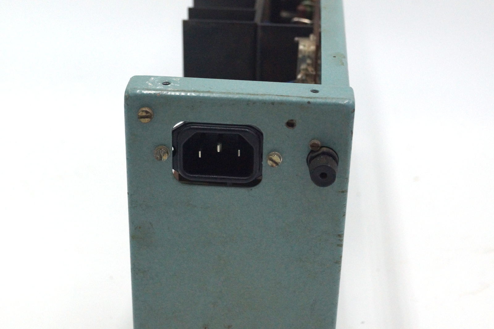
Finally the power inlet I replaced with a standard C14 socket which fit almost perfectly.


Testing
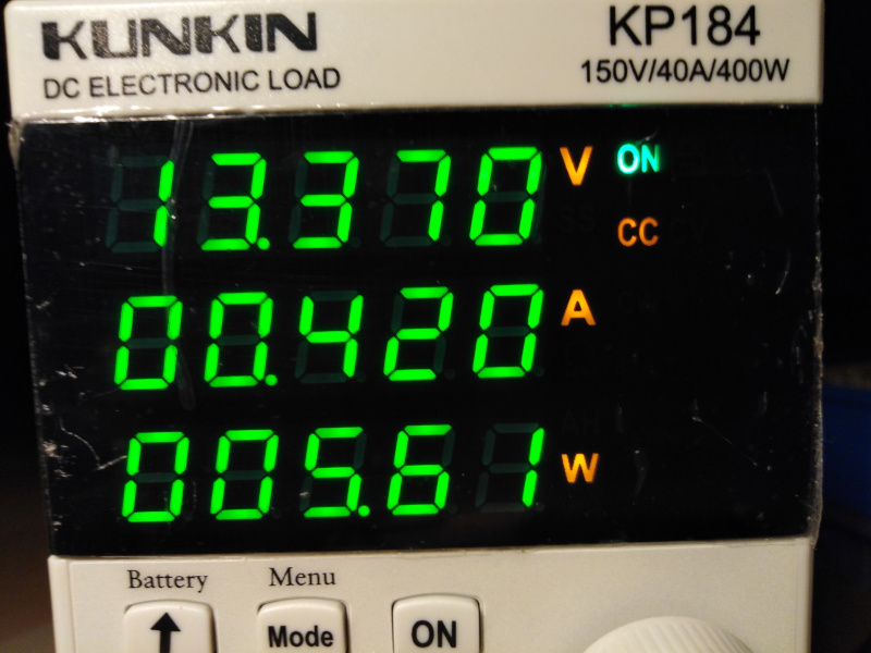

Starting at 430mA on either output the overload indicator comes on. The regulated output stays fairly close to -14V over the whole range.
Improvements
I added polarity protection diodes to the outputs, to protect the circuit in case I accidentally hook it up wrong. I used east German SY360/8 diodes for this since I have a full belt of old-new stock of those.
Also I added a thermal fuse metal oxide varistor from TDK (NT14) to the input in order to protect the primary transformer winding against voltage surges. This is not intended to be a full surge protector, just to protect the transformer a little bit, since I don’t know how well the insulation would hold up over surges.
Update 28.12.2023
I took it apart again to write down the values of the resistors in case any of them blow up. While doing so I wanted to apply thermal paste to the main transistor. While doing so I noticed that the heat sink is not actually spot welded, but just individual pieces. They had some oil (?) residue on them, I cleaned them up and applied thermal paste.


Also here is a picture of the circuit board, which I for some reason did not include in the above:
