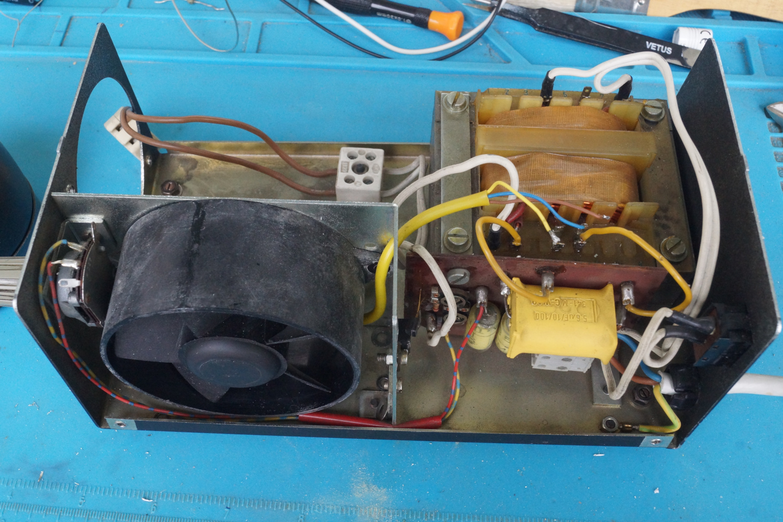
Circuitry Overview
The circuit is super simple, there is a motor run capacitor for the AC fan which is connected to a separate tap on the transformer and insulated from the rest of the circuitry. A small triac dimmer on the secondary 12V AC side using a MAC223 triac and another 3 pin TO-92 device which I think is either another triac or a SCR two film capacitors and a couple potentiometers. Haven’t bothered to reverse engineer the exact circuit, as the PCB can’t be removed without desoldering all the wires which I did not want to bother with at this time.
The lamp in mine was a OSRAM HLX 64618 (85W 12V) which I think is slightly too high. My guess is that it was designed for OSRAM HLX 64615 (75W 12V) lamps, as the total power rating is supposed to be 80VA according to the sticker on the back. Any other dimmable 12V cold reflector lamp with a G5,3 or G6,35 socket however will work as well including LED lamps.
Fan replacement
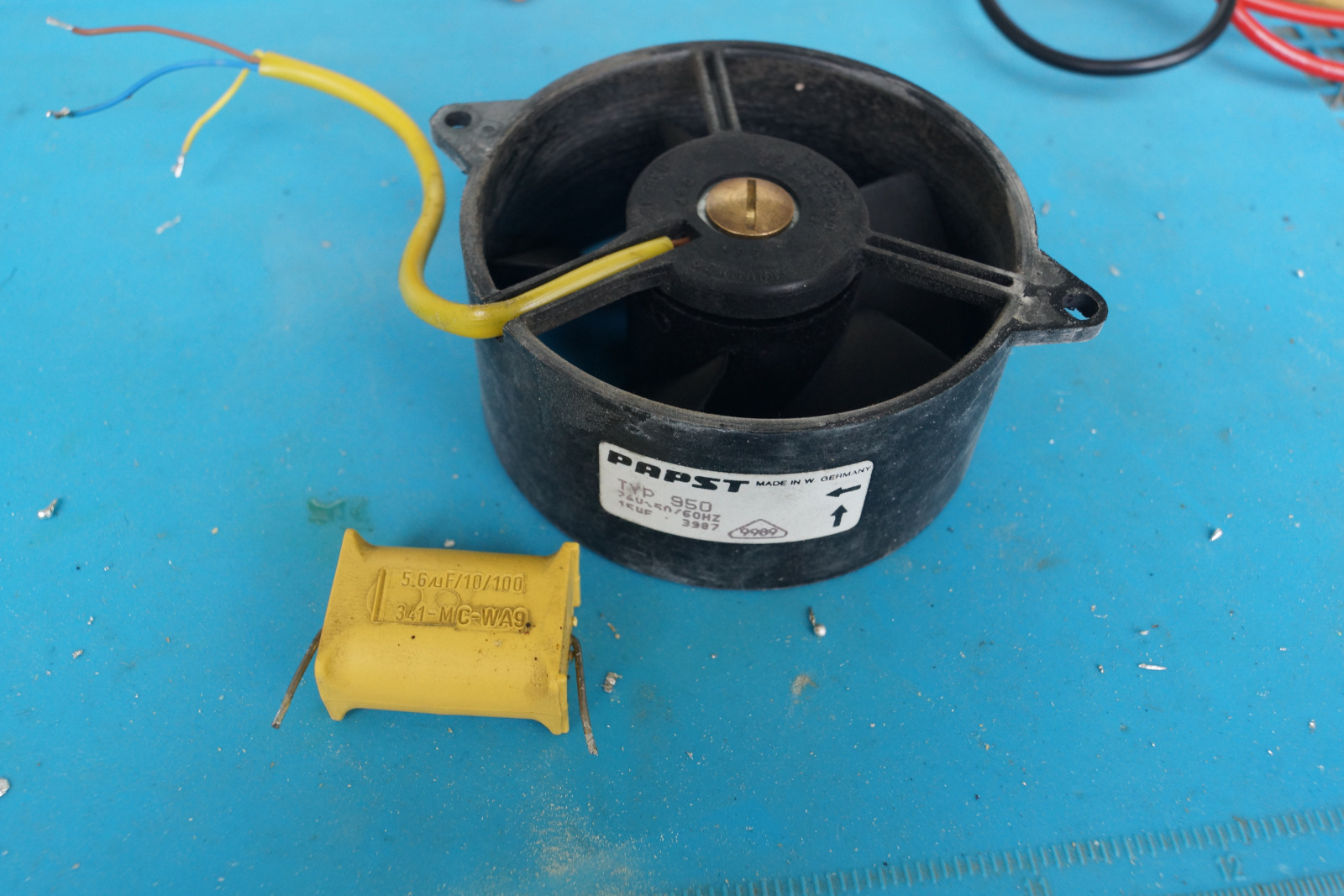
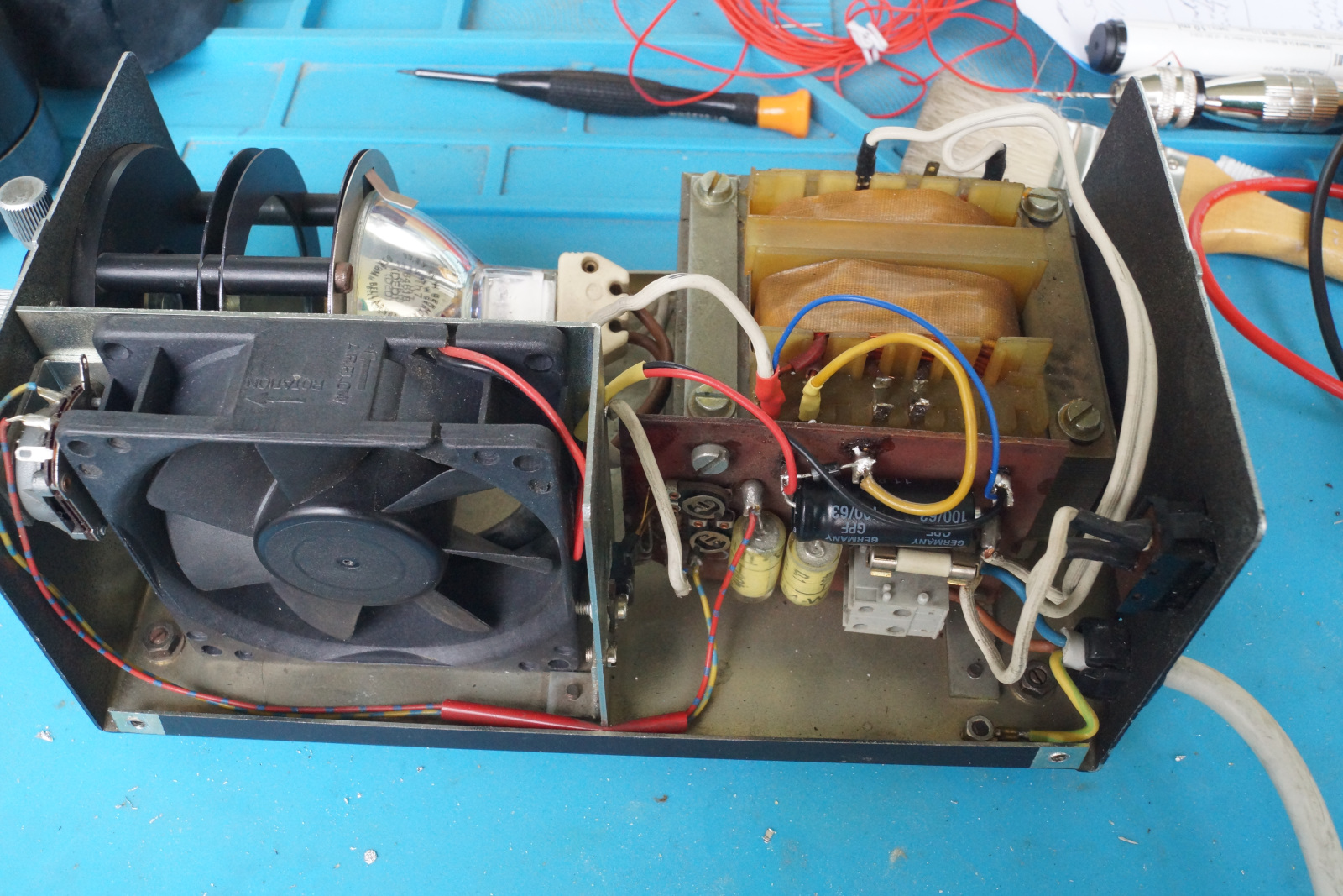
The AC fan (Papst Typ 950 / 74V AC) was at this point fairly loud and got excruciatingly hot. So I figured to replace it. I chose to make it so that I can use standard 12V fans (80x80mm) which are the most easy to get. To do this I replaced the motor run capacitor with an electrolytic capacitor and added a diode from one of the 12V transformer tabs going into the circuit board right next to it and added a wire on the low side of the capacitor to the other transformer tap. Giving me an unregulated half-wave rectified 12V DC supply.
Here the capacitor sizing is crucial, such that the nominal voltage does not get too high for the fan. I found a 100µF capacitor to yield around 11.6V with the fan load. If I put in another fan that takes less current (this DC fan is quite old itself), I may have to scale down even further to ensure the voltage does not go over say 14V. When the lamp is on full power, the voltage may drop by a volt and the fan gets a little bit slower but still moves enough air.
The fan I’m using was out of my fan bin and I think I got this out of an old computer power supply, according to what I could find it has a rating of 30m3/h (18 CFM). From a “hand test” this feels like around what the old AC fan had and as such I would not use anything below this.
I left the 40V secondary winding on the transformer which was for the original AC fan unconnected.
One problem I found is that the PCB will get fairly warm when the lamp is running on full power, as such at some point the electrolytic capacitor will dry out. This will be examinable by the fan going slower with the lower voltage over time. A permanent solution may be a film or foil capacitor, but I don’t worry about this for now.
EMC Supression Capacitor
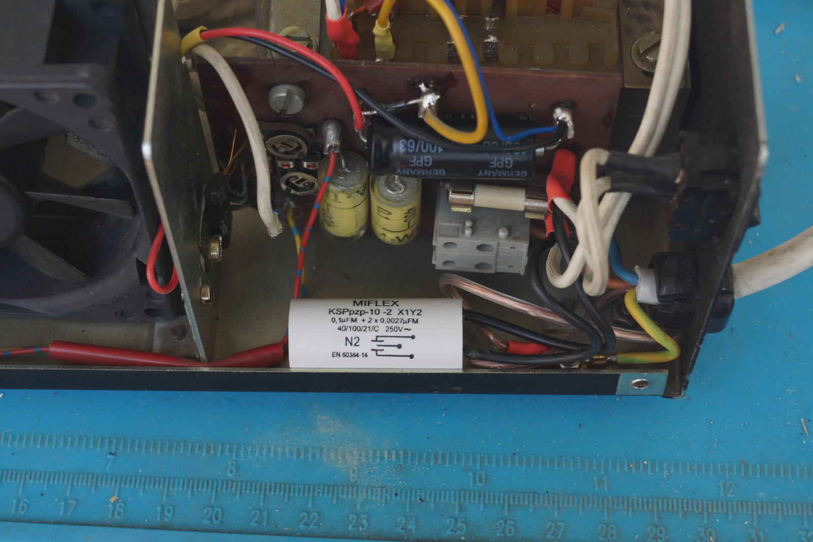
I noticed a lot of electric noise in the transformer, whenever the triac circuit on the secondary side is dimming down the lamp. So I figured to add a noise suppression filter. It’s a X1Y2 capacitor filter from Miflex (KSPpzp-10 -2 X1Y2) I connected it to where the AC input goes to the circuit board for the fuse before the main power switch. This means the capacitor is always connected across the line when the unit is plugged in regardless of whether it is switched on or not, though. However this shouldn’t be a problem since I trust those modern capacitors.
While on it I also added shrinking tubes around the PCB terminals the AC line is soldered onto, as these were exposed before.
The audible noise from transformer is now pretty much completely gone when the dimmer is active. I was surprised about how well this worked out myself.
Schölly / VOLPI / Olympus Adapter
My source had a 20mm connector, however I had some existing attachments with the 16mm connector used by Schölly and others. In order to use these I 3D printed myself a bushing. This works, as the source has a heat protective glass between the bulb and the lens and the mount in the front doesn’t get hot. It gets warm (~say 40C) at most and this is not a problem for PLA filament.
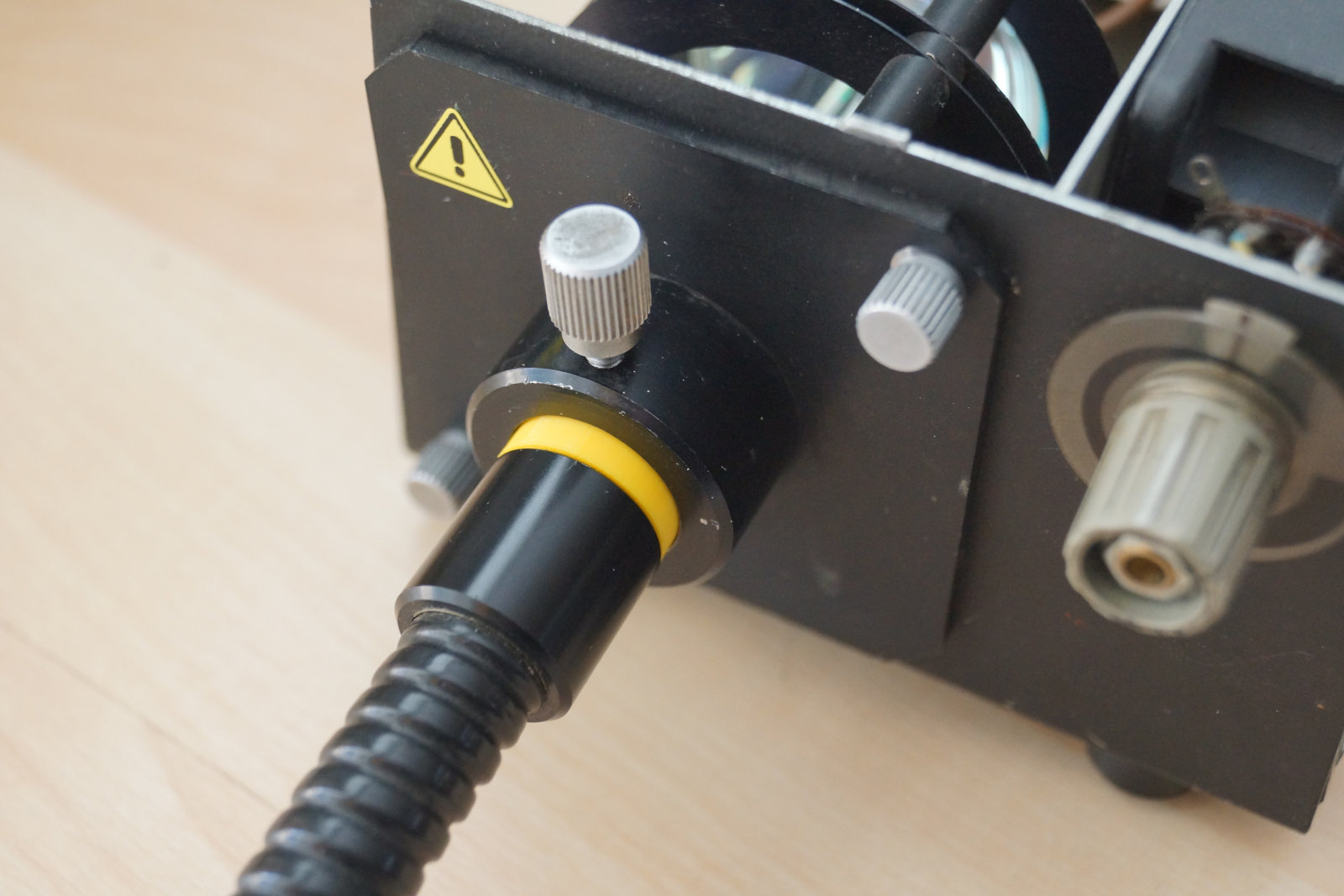 (Yellow one is the adapter bushing)

Important: You have to adust the offsets in the file, that is the -0.2 and -0.3 in the two cylinder directives,
respectivly to match your printer nozzle, such that the inner and outer diameter are fitting properly. The offsets
in the OpenSCAD file work fine for my Anycubic Vyper with a 0.4mm nozzle at 0.1 layer depth in the slicer.
Download: OpenSCAD file STL for Anycubic Vyper