Circuit
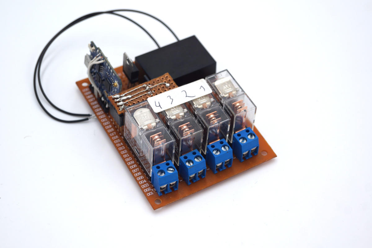
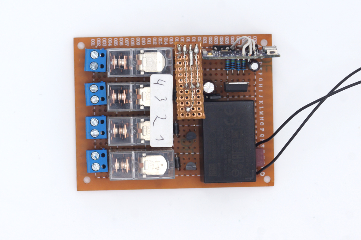
Nothing much to say, it’s fairly standard. The relays are switched using BC517 darlington transistors. The unit is powered using a 230V to 12V AC/DC SMPS, the 5V for the ESP8266 board is derived from a standard LM7805.
I used a WEMOS D1 I desoldered from another project, unfortunately a couple of the output pins didn’t work (probably damaged an internal trace while desoldering). So I used some wires to connect the signals to the pins that are working. A problem with those boards, or with ESP8266 boards in general is that some pins are in HIGH state on startup, meaning some of the relays will initially close for a split second. To solve this problem I’m going to build a small on-delay circuit for the relay coil voltage.
Delay Circuit (Update 11.12.2021)
Since the aforementioned problems with default HIGH pins on the ESP8266 I built this siple on-delay circuit, that will keep the relays initially off. I built this as a small stand-up board with a FS04 SCR. The capacitor will trickle charge through the 330kΩ resistor, once the voltage reaches >800mV or so the SCR will trigger, passing the VCC to the relay coils.

Update 24.12.2021: Here is a picture of the delay module:

MQTT Topics
The device listens to the following topics:
<device>/relay/set/<no>Set the given relay.<device>/relay/unset/<no>Unset the given relay.<device>/relay/toggle/<no>Toggle the state of the given relay.<device>/system/resetReset the ESP8266.
The device itself sends a status message after on every command, as well as after each second on the
<device>/status topic.
Here is an example of a <device>/status payload:
{"chipId":1234567,"device":"relay4-mk1","relays":[true,true,true,true]}
Firmware
Here is the complete source code, I’m using the ArduinoJson and EspMQTTClient packages.
#include <ArduinoJson.h>
#include "EspMQTTClient.h"

static const int RLY[] = {D1, D6, D7, D8};
static bool RLYSTATE[] = {false, false, false, false};

/////////////////////////////// Adjust the following
#define BASETOPIC "relay4-mk1-1234567"

EspMQTTClient client(
  "SSID",
  "SSID_PASSWD",
  "MQTT_BROKER",
  "MQTT_USER",
  "MQTT_PASSWD",
  BASETOPIC
);
/////////////////////////////// End of adjustment code

void emitStatus();

void setup() {
  //Serial.begin(9600);

  for(int i = 0; i < 4; ++i) {
    pinMode(RLY[i], OUTPUT);
    digitalWrite(RLY[i], LOW);
  }
}

void emitStatus() {
  StaticJsonDocument<200> json;
  String out;

  json["chipId"] = ESP.getChipId();
  json["device"] = "relay4-mk1";
  JsonArray array = json.createNestedArray("relays");

  for(int i = 0; i < 4; ++i) {
    array.add(RLYSTATE[i]);
  }

  serializeJson(json, out);
  client.publish(BASETOPIC "/status", out);
}

void onConnectionEstablished() {

  client.subscribe(BASETOPIC "/relay/#", [] (const String& topic, const String &payload)  {
    String base = BASETOPIC "/relay/";
    String sub = topic.substring(base.length());
    int id = sub.charAt(sub.length()-1) - '0';
    bool state;

    if((id < 1) || (id > 4)) {
      return;
    }

    state = RLYSTATE[id-1];

    //Serial.println(sub);
    //Serial.println(id);

    switch(sub[0]) {
      case 's':
        state = true;
        break;
      case 'u':
        state = false;
        break;
      case 't':
        state = !state;
        break;
      default:
        return;
    }

    RLYSTATE[id-1] = state;
    digitalWrite(RLY[id-1], state ? HIGH : LOW);

    emitStatus();
  });

  client.subscribe(BASETOPIC "/system/reset", [] (const String &payload)  {
    ESP.reset();
  });
}

void loop() {
  static unsigned long idle = millis();

  client.loop();

  if((millis() - idle) > 1000) {
    emitStatus();
    idle = millis();
  }
}